Getting Started
OpenDTU supports the ESP32 family of microcontrollers.
Depending on the inverter to be addressed, different RF modules are required.
- The HM series requires the NRF24L01+ module
- The HMS/HMT series requires the CMT2300A module
Please see the inverter overview to see if your inverter is supported and to determine the required RF module.
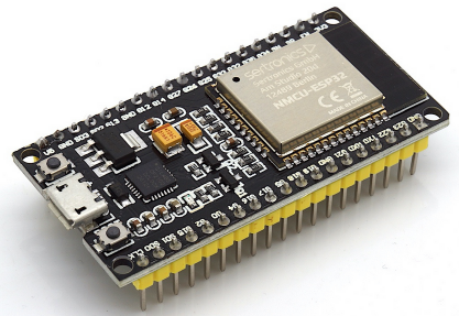
For an easy start, use a "NodeMCU32 ESP32 DEVKIT DOIT" or "ESP32 NodeMCU Development Board" with an ESP32-S3 or ESP-WROOM-32 chipset on it.
Sample Picture:
Boards with Ethernet-Connector and Power-over-Ethernet are also supported. For example Olimex ESP32-POE or LilyGo T-Internet-POE
Steps to build your own DTU
Use of GPIOs
In general, ESP32 chips allow to use any function on any GPIO pin. There are a few restrictions, which are documented at the respective ESP32(-S3) DevKit subpages. Freely wire the logic pins between your ESP32(-S3) module and peripheral components. The important bit is to create and use a matching device profile.
- Determine the RF module you need
- Get a ESP32 module.
- Use a power suppy with 5 V and 1 A. The USB cable connected to your PC/Notebook may be powerful enough or may be not. Also the quality of the used USB cable might have an impact.
- Wire the module and RF module
- Wire a optional display
- Wire optional LEDs
- Flash the firmware via USB
- Create, upload, and select a matching device profile which describes your hardware (or look at a profile first and connect the logic pins accordingly).